Link to YouTube video Piezoelectric vibration measurement systems (PVMS) are conventional equipment for condition monitoring but they are high cost due to equipment and cabling costs. Why don’t we use commercial-off-the-shelf (COTS) micro-electro-mechanical system (MEMS) vibration measurement system (VMS) as an alternative? These COTS-MEMS VMS have lower cost, no external power/communication cables, and are self-contained with the sensor, power and data storage in a single portable enclosure.
This work is one of very few to compare the performances of a wireless COTS-MEMS VMS, COTS-MEMS VMS with local storage only and a PVMS. Performance of all VMS is measured in terms of frequency spectrum comparison, noise floor, data loss, and use conditions such as mounting and data collection. Testing was conducted in a) a controlled environment using an isolated vibration shaker, and b) two industrial applications on a centrifugal fan and pump. Results show the COTS-MEMS VMS have comparable results with PVMS in the range of 5 Hz to 1.5 kHz sinusoidal input on a vibration shaker. The pump test demonstrated that the high noise floor on both the COTS-MEMS VMS prevented detection of operating frequency. An imbalance was induced in the fan to increase the amplitude at the operating frequency by an order of magnitude which both the COTS-MEMS VMS were able to detect. The wireless COTS-MEMS VMS suffers from data loss due to the use of the UDP protocol. Post-processing a sample with data loss causes spectral leakage and higher noise floor in the frequency spectrum and it must be avoided. Both COTS-MEMS VMS perform comparably with the PVMS when the vibration amplitude is discernible from its noise floor and when there are no losses in the data sample. Author: Carlin Lapuz, Master of Professional Engineering (Mechanical) 2020
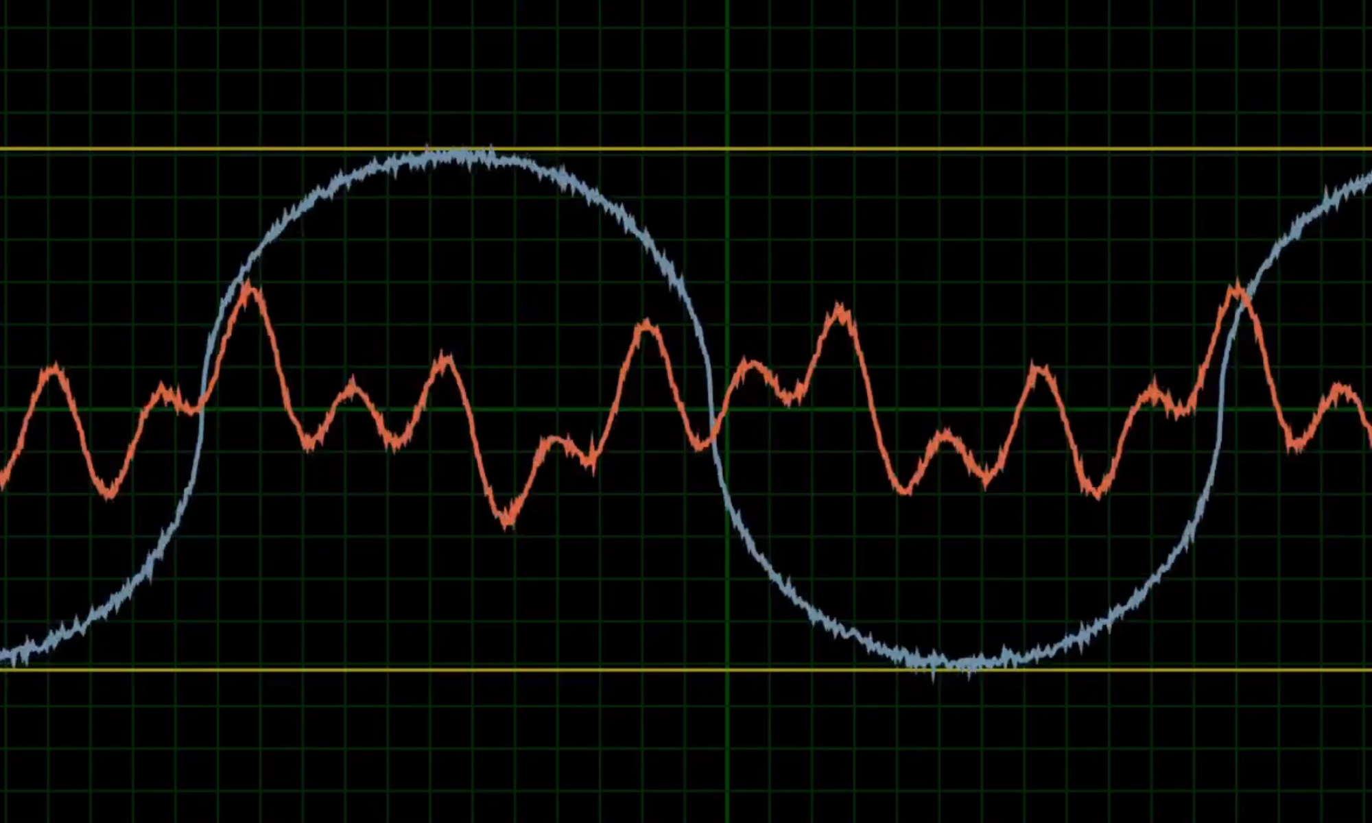
Link to YouTube video Rolling element bearings are in most of the rotating equipment that makes up the modern world. The downtime of rotating equipment due to bearing failure can be prevented by using sensor information to predict faults. However, a replicable bearing failure method is necessary for operators to interpret sensor data and reliably detect faults in industrial equipment. Bearing failure testing is conducted on small scale test rigs and often have a poor explanation of the experimental design. This study develops a method for inducing bearing failure on an industrial piece of equipment using lubrication and contamination of the bearing to induce failure in a short amount of time. The findings from this research show that failure can be induced through mixed grease contamination within one hour of testing. There are some great photos of vibration analysis resulting from this.
Author: Aseem Maroo, Masters of Professional Engineering (Mechanical) 2020
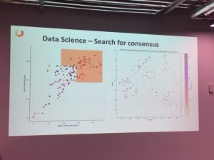
Great talks at the Data Science week 2019 event at FLUX on Open data/ Open innovation. Thanks to Daniel Cesar from Newcrest on orphans of innovation and other notions, Jess Robertson about Evergreen challenges and the power of consensus and Melinda Hodkiewicz on managing industry’s concerns about releasing data.
‘Innovators find it difficult to access sites to prove up results and miners are averse to trialling/introducing innovation without proven results’ -METS Ignited 2017
The UWA Living Lab project aims to help bridge this gap.
The Living Lab project funding was officially announced recently at the METS Ignited event at the CORE Innovation Hub. The launch funding is being supplied through the METS Ignited Collaboration Project Fund, from the BHP Fellowship for Engineering for Remote Operations. This is a partnership with CORE Innovation Hub and the UWA Facilities Management group.
This one-day workshop 13 July 2018 brought together the Machine Learning and Formal Methods communities. Here is a summary of some take-aways. Highlights were the talks by Pushmeet Kohli from Google DeepMind UK, Alison Lowndes from NVIDIA, and Adnan Darwiche UCLA. Melinda Hodkiewicz (SHL)and Ashwin D’Cruz (ex-SHL now working for Calipsa in London) attended. https://www.floc2018.org/summit-on-machine-learning/.
Pushmeet Kohli (Google DeepMind): Challenges for AI are to ensure it is a) robust to adversaries, b) generalises well to variations in the real world, c) it is fair, d) it is compliant with regulations. When talking about ‘fairness’, he split the discussion into the “What do we mean by fair?” and “How to make AI fair”. He did not answer the “what” question. Instead saying that “this needed to be set in regulations”. As far as the “how”, Kohli suggested three steps 1) rigorous testing, 2) developing robust AI, and 3) verifying AI systems. A significant challenge for AI is that test set evaluation approaches commonly used in ML are inappropriate for 1) adversarial environments and 2) safety critical domains. In safety critical domains loss functions are unbounded. Also you would need a lot of samples of bad events for test set evaluation, and we can’t afford to do this. He then gave some examples of work his team at Google is doing (see his recent ICML, ICLR and NIPS papers) and left us with the idea that we might need a new language for AI which has suitable inductive bias (set of assumptions that the learning algorithm uses to predict outputs given inputs it has not encountered) and with the right expressiveness to describe what’s going on.
Comment: Melinda asked the room if there was anyone at the workshop working for legislators or regulators; there was not. It is not clear how legislators are going to develop workable regulations and regulators have the capacity to assess practice against these regulations without a good understanding of the issues being discussed at these types of events.
Alison Lowndes (NVIDIA): NVDIA has developed massive simulation platforms and Alison talked about their work on Jetson Xavier, an AI computer for autonomous machines delivering GPU workstation performance in a single embedded module https://developer.nvidia.com/jetson-xavier-devkit. She observed that while Reinforcement Learning was highly fashionable (80 papers/day published on arXiv), it is not commercial yet. Classical ML (SVM, MLP, GBDT) are still very relevant and widely used. Convolution neural networks are widely used. She expressed concern about the “common person’s voice in the room” and suggested that philosophy and psychology will become more important. Finally relevant for the SHL and Makers she said that educational institutions can get a free DevKit from NVDIA https://developer.nvidia.com/teaching-kits
Andre Platzer (Carnegie Mellon) talked on ‘safe’ reinforcement learning via formal methods with a focus on safety critical systems. How do you demonstrate that the algorithm is “provably safe”? He talked about the need to 1) learn safety, 2) learn a safety policy, and 3) verify and about the issue of “what if the model is incorrect”? As far as safety policy, this appears to be based on the idea of “have we seen this output before and it was ok, then it should be safe, given the same context”, how do we know to trust this and how do we know if the context has changed? Andre runs the Logical Systems Labs http://www.ls.cs.cmu.edu/ and has a text book on Logical Foundations of Cyber-Physical Systems.
Sumit Gulwani from Microsoft talked abotu their PROSE kit https://microsoft.github.io/prose/. This is about programming by examples – the automatic generation of programs from input-output examples. It can build programs in various languages such as Python/R/C# and some of its functionality is baked in Excel. Some scripts that are now tedious to write can be automated.
Marta Kwiatkowska (Oxford) talked about her team’s work on ‘safety verification for deep learning networks with proven guarantees’. She made the point that while there are an infinite set of possible outcomes we only measure ‘accuracy’ on a finite data set. She demonstrated how deep learning networks are unstable to adversarial perturbations using image processing of a car sign (plenty of papers on this on arxiv) and asked ‘how can we verify that such behaviour cannot occur’. Marta’s group at Oxford is involved in modelling and automated verification techniques for software systems. One of the current projects in her group is safety and trust for mobile autonomous robots. http://www.cs.ox.ac.uk/people/marta.kwiatkowska/research.html.
Adnan Darwiche from UCLA presented on “what just happened in AI”. It draws on his recent paper “Human-Level Intelligence or Animal-Like Abilities” https://arxiv.org/abs/1707.04327. He made a number of interesting observations 1) Lots on new AI applications, 2) AI has been around >50 years, 3) The AI curriculum is almost unchanged. Essentially every behaviour can be captured to some extent by a function. We are now building bigger functions and we have more data. A deep learning NN is a function and architecting the structure of a NN is function engineering. Next he moved onto how our perception of value has changed. Model-based approaches try and understand a system whereas ML models translate without insight. We have realised in many cases (e.g. social media) you don’t need the understanding to be useful. The ease at which we can get results that may be the same or only slightly better than what we can do with model based methods is very attractive. However he warned about the growing gap between hype and reality and reminded the audience of a period he described as the “AI winter”. He warned about a lost generation of AI researchers who are well versed in NN models but not in Logic, the need to understand the limitations of function-based approaches and to characterise deep learning functions in a scientifically precise manner. It’s worth reading his paper from the link above for a fully discussion of his concerns.
This week Melinda talked with Dr. Beatrice Alex who is in computational linguistics at the University of Edinburgh. I learned a lot about when and how to include subject matter experts in the NLP and semantic object identification pipeline. We can take some of the lessons she learned in their digital humanities project into our Siri for Maintenance project. Beatrice’s homepage is http://homepages.inf.ed.ac.uk/balex/
The initial focus for this project will be in understanding and designing a circuit able to transmit a wireless signal with a low input voltage. Using a blog article on a simple scavenger ring as a starting point, it will be the team’s responsibility to analysis, modify and improve on the basic functioning ring that was created. This will be achieved by extensive use of literature and other research to create a much more extensive and functioning circuit which has been designed with a more comprehensive level of examination. Once completed, a secondary circuit will need to be designed to harvest a particular source of energy to power the circuit. The options available for this project include peltier, piezo electric, electromagnetic and magnetic coil. For this part of the project the optimisation and testing of the allocated energy source, used to power the sensor will be the main component of the thesis. The overall result will hopefully be a small device that can emit a signal from small amounts of energy harvested from the particular source.
The traditional methods for high frequency data analysis involve many piezoelectric sensors, signal amplifiers and spectrum analysers the size of a modern day desktop computer. However, with the arrival of low cost and easy to use microcontrollers and Micro Electromechanical Systems (MEMS), perhaps it’s time to reconsider some of the traditional methods. This blog post aims to outline some of the challenges, limitations and success encountered whilst trying to use a combination of microcontroller and MEMS devices for condition monitoring.
The equipment:
Arduino MEGA 2560: . The large user community along with extensive libraries available make this an ideal choice for experimentation.
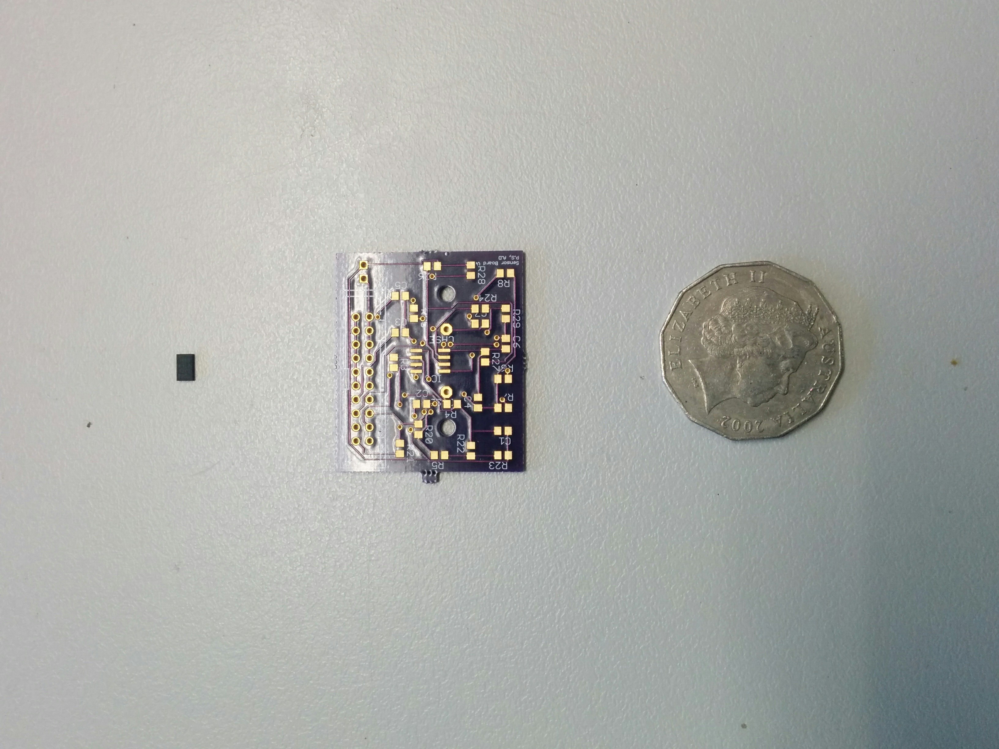
ADXL345: The ADXL345 is a small, thin, low power, 3-axis accelerometer with a measurement range of upto ±16 g.
ADXL345 (Left) & PCB. Coin for scale.
Thanks to the advances in rapid prototyping, it is incredibly easy to produce PCB’s in low quantities whilst keeping cost to a minimum. We had designed and manufactured our own PCBs to support this project. The PCB houses the accelerometer, a temperature sensor, a voltage and current sensor and a various other electronics. This test setup cost us <$100.
Challenge #1: Data storage:
The Arduino lacks an onboard flash storage. Therefore it requires an external storage space to store the data. An SD card shield is the simplest solution to overcome this problem. This method however, has one big disadvantage and that is the speed at which data can be written to an SD Card. Every time the Arduino has new data to be written to the SD Card, a file in the SD Card has to be opened, the data written and then closed. Failure to close it at the end of each data entry may result in corrupt data. The process of writing to an SD Card is slow and is subsequently one of the biggest limitations to recording high frequency data.
Solution: Buffer memory
The Arduino has 512kb of Random Access Memory (RAM) which has a much higher read/write speed than any external flash storage. So by writing to this memory, then transferring it in chunks to an external flash storage at once, we are able to record data at much higher frequencies. However, the measly 512kb RAM posses severe limitations to the number of data points that can be obtained. We are limited to around 500 data points before the the RAM fills up and requires to be transferred to the SD Card. The Arduino is also incapable of collecting any new data whilst this transfer is in progress. This means that the vibration data is not continuous and can only be obtained in small chunks. There are methods to increase the RAM of the Arduino using external RAM modules, which would enable us to increase our sample size significantly. But that is a different challenge on it’s own, and one we will hopefully tackle in the near future.
Challenge #2: Obtaining consistent data
This issue is most relevant for vibrational data.
The ADXL345 supports a maximum Output Data Rate (ODR) of 3200hz on SPI and 1600hz on I2c. Our test rig is currently configured to use I2C. To understand this challenge, some knowledge of the Arduino’s operation is required: The Arduino continuously carries out a set of instructions in a conditional loop. It can be configured to request data from it’s sensors each time the loop is executed. The time taken to complete the instructions inside the loop is very inconsistent and therefore, the time interval between each data point can vary. This inconsistency can severely affect some time sensitive data such as vibrational data. Without a fixed ODR, the vibration data is essentially useless.
Solution: FIFO Buffer
Luckily, one of the ADXL345 chip’s distinguishing features, is the inclusion of a First In First Out (FIFO) buffer. The chip continuously collects data at a fixed rate, stores it in it’s FIFO buffer, and triggers a watermark when the FIFO buffer is full. The Arduino can be configured to continuously scan for this watermark and transfer the data from the FIFO buffer onto it’s RAM upon the watermark’s signal. This guarantees a fixed, consistent ODR. Ofcourse, this only works because the Arduino can poll the accelerometer at a faster rate than the accelerometer is collecting data.
Challenge #3: Accuracy
Coming soon: We are testing this and will update shortly.
So recently I started using Microsoft (MS) Access which is the Database Management System (DBMS) in the MS Office Suite. While it presented a very interactive and pleasant graphical user interface (GUI), I started running into problems when I wanted to access the data online. While it was straightforward enough to do so with SharePoint, my team and I didn’t want to go down that road as we wanted the database to integrate well with other parts of web development and not be constrained to Sharepoint. That’s when a colleague of mine, Joanna Sirkoska landed upon ADOdb which allowed us to use PHP to connect to an Access Database.
In this post, I’ll briefly go through how you can connect to your chosen Access database and display the information within it using queries. The script to do so is quite straightforward and you can find it at this link. With this script you’ll either need to modify it to use your database or use the same database that I did which I have provided here.
I’ll run through some of the code here which should hopefully make things clearer if the comments in the script are not clear enough.
First of all you need to make sure you have the following line before trying anything else:
include(‘C:\wamp\www\adodb5\adodb.inc.php’);
To do so, check out the ADOdb link at the start and download the package. Then decide where you want to put it and make sure you change the line to reflect your path choice.
Then we need to connect to the chosen database:
$conn = new COM(“ADODB.Connection”) or die(“Cannot start ADO”);
The first line creates an instance of the ADO connection object. You’ll need to edit the second line to match the database you choose to use. Finally the last line opens a connection to this database.
Next we have to execute a query:
$query = “SELECT * FROM tblEquipClass”;
$rs= $conn->execute($query);
I’ve chosen a fairly simple query which which get all the information contained within the table ‘tblEquipClass’. Then I execute the query storing the results within the variable $rs.
An easy way to view the information contained within $rs is printing out the information within it:
while (!$rs->EOF) { print $rs->fields[2].'<BR>’; $rs->MoveNext(); }
This while loop allows you to iterate through each line of data from the table. We then print only information from the third column out.
Finally we can close the connections made previously but that is optional.
There you have it! Now you can design your tables using the nice GUI MS Access provides but allow greater connection to your database using PHP. Leave a comment if you found this useful or have any queries.
So recently we were doing some data collection with an Arduino mega and an accelerometer, specifically the ADXL345. Now the datasheet on the ADXL345 stated that the maximum sampling frequency is 3200 Hz but we found that our data points we only coming through at about 900 Hz. After some digging around the web, we found a potential cause.
Although the Arduino should be able to handle up to 400 kHz I2C communication, it is by default limited to 100 kHz in a particular library header file. Now 100 kHZ should be more than enough to sample a device which is supposed to be capable of 3200 Hz sampling but it’s not as straightforward as that. We think that although 100 kHz is the I2C bus speed, there is still going to be some time initiating communication. Depending on the library you choose to use. there could be several back and forths between the Arduino and the ADXL345 before any data is actually exchanged.
We found however that by making the change to 400 kHz, we were able to obtain data at 2600 Hz which while not maxed out, is still a significant improvement! Perhaps the remainder is due to the aforementioned communication overhead. Here’s what we did to obtain the increased bus speed as laid out at this link.
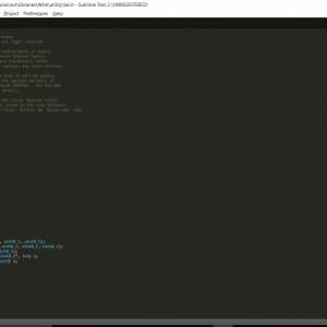
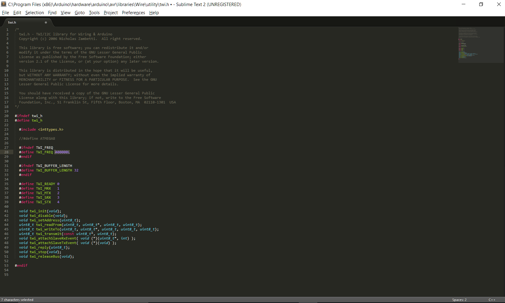
Locate the twi.h header file at this location: C:\Program Files (x86)\Arduino\hardware\arduino\avr\libraries\Wire\utility.
Now instead of just telling you the full path, I’ll provide a picture as well so you can confirm you’ve found the correct file (note the path in the top right corner).
Once you’ve located the file, note the highlighted section. This is the default value provided when you download the Arduino software. Change the 100000L to 400000L. It’s a simple as the picture below!
And that’s pretty much it!
You’ll need to let Arduino recreate the associated object files but this is simply a matter of restarting the Arduino IDE. You should notice an increase in your I2C communication! Mind you that you’ll have to be talking to a device capable of making use of this increased speed (like we had with the ADXL345).
I won’t claim to know all the maths behind this so if you know more, please share your knowledge with us in the comments section! Alternatively if you found this a useful link, leave that in the comments too!

You must be logged in to post a comment.