The traditional methods for high frequency data analysis involve many piezoelectric sensors, signal amplifiers and spectrum analysers the size of a modern day desktop computer. However, with the arrival of low cost and easy to use microcontrollers and Micro Electromechanical Systems (MEMS), perhaps it’s time to reconsider some of the traditional methods. This blog post aims to outline some of the challenges, limitations and success encountered whilst trying to use a combination of microcontroller and MEMS devices for condition monitoring.
The equipment:
- Arduino MEGA 2560: . The large user community along with extensive libraries available make this an ideal choice for experimentation.
- ADXL345: The ADXL345 is a small, thin, low power, 3-axis accelerometer with a measurement range of upto ±16 g.

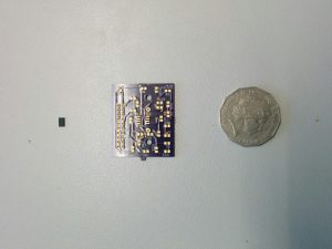
Thanks to the advances in rapid prototyping, it is incredibly easy to produce PCB’s in low quantities whilst keeping cost to a minimum. We had designed and manufactured our own PCBs to support this project. The PCB houses the accelerometer, a temperature sensor, a voltage and current sensor and a various other electronics. This test setup cost us <$100.
Challenge #1: Data storage:
The Arduino lacks an onboard flash storage. Therefore it requires an external storage space to store the data. An SD card shield is the simplest solution to overcome this problem. This method however, has one big disadvantage and that is the speed at which data can be written to an SD Card. Every time the Arduino has new data to be written to the SD Card, a file in the SD Card has to be opened, the data written and then closed. Failure to close it at the end of each data entry may result in corrupt data. The process of writing to an SD Card is slow and is subsequently one of the biggest limitations to recording high frequency data.
Solution: Buffer memory
The Arduino has 512kb of Random Access Memory (RAM) which has a much higher read/write speed than any external flash storage. So by writing to this memory, then transferring it in chunks to an external flash storage at once, we are able to record data at much higher frequencies. However, the measly 512kb RAM posses severe limitations to the number of data points that can be obtained. We are limited to around 500 data points before the the RAM fills up and requires to be transferred to the SD Card. The Arduino is also incapable of collecting any new data whilst this transfer is in progress. This means that the vibration data is not continuous and can only be obtained in small chunks. There are methods to increase the RAM of the Arduino using external RAM modules, which would enable us to increase our sample size significantly. But that is a different challenge on it’s own, and one we will hopefully tackle in the near future.
Challenge #2: Obtaining consistent data
This issue is most relevant for vibrational data.
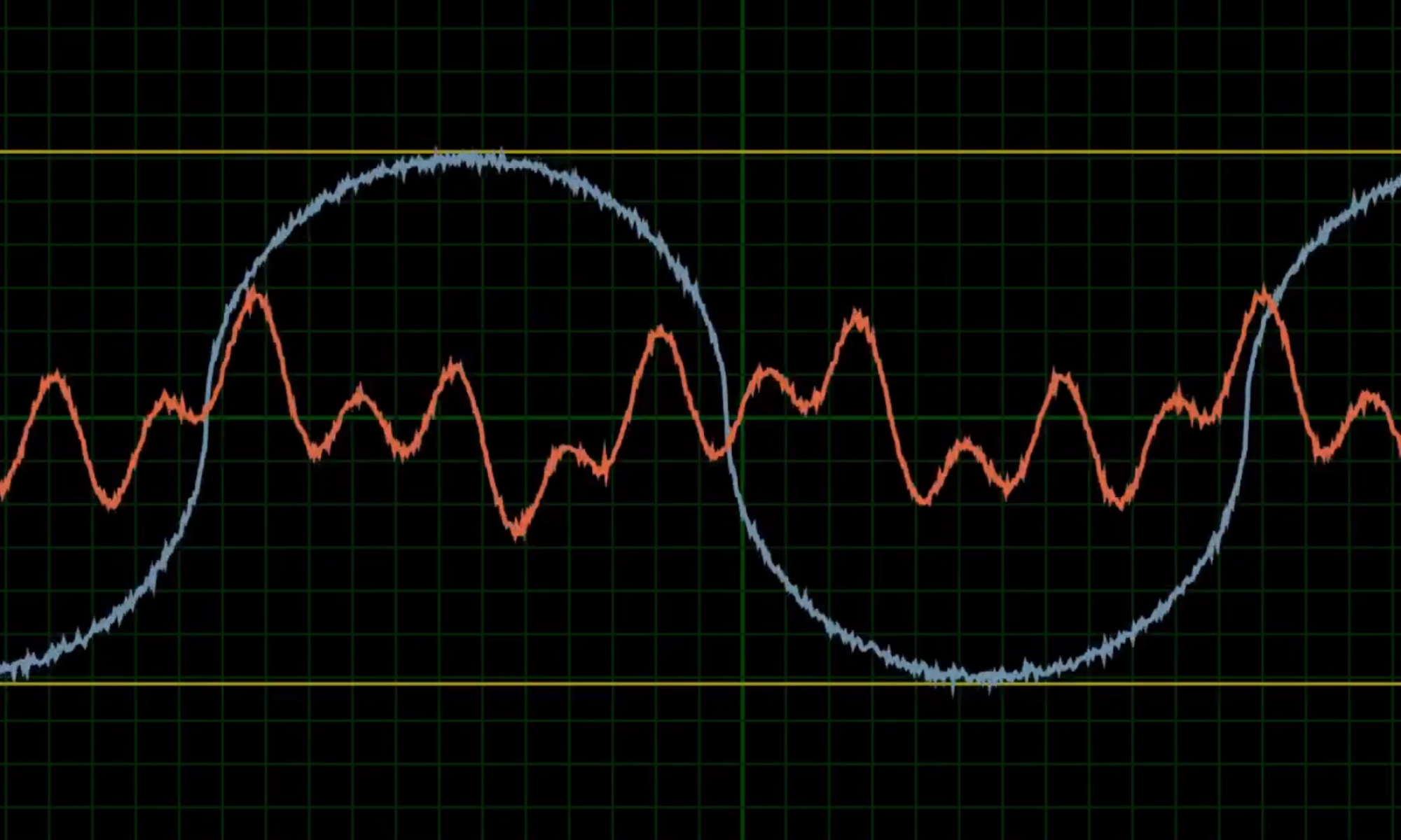
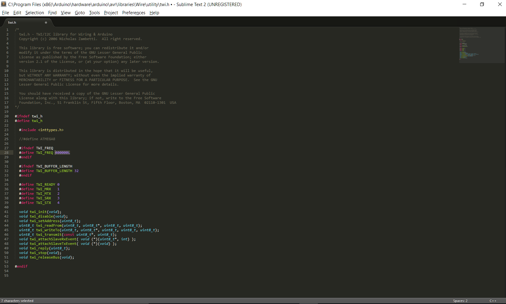
The ADXL345 supports a maximum Output Data Rate (ODR) of 3200hz on SPI and 1600hz on I2c. Our test rig is currently configured to use I2C. To understand this challenge, some knowledge of the Arduino’s operation is required: The Arduino continuously carries out a set of instructions in a conditional loop. It can be configured to request data from it’s sensors each time the loop is executed. The time taken to complete the instructions inside the loop is very inconsistent and therefore, the time interval between each data point can vary. This inconsistency can severely affect some time sensitive data such as vibrational data. Without a fixed ODR, the vibration data is essentially useless.
Solution: FIFO Buffer
Luckily, one of the ADXL345 chip’s distinguishing features, is the inclusion of a First In First Out (FIFO) buffer. The chip continuously collects data at a fixed rate, stores it in it’s FIFO buffer, and triggers a watermark when the FIFO buffer is full. The Arduino can be configured to continuously scan for this watermark and transfer the data from the FIFO buffer onto it’s RAM upon the watermark’s signal. This guarantees a fixed, consistent ODR. Ofcourse, this only works because the Arduino can poll the accelerometer at a faster rate than the accelerometer is collecting data.
Challenge #3: Accuracy
Coming soon: We are testing this and will update shortly.
Praveen Sundaram
Research Assistant
System Health Lab, UWA


You must be logged in to post a comment.