ADT Chamber: Preliminary Test Data

Preliminary tests on the operating range and control of the environmental variables within the chambers has been conducted. Results are very positive, with humidity generation and control exceeding expectations, and temperature extremes being easily attainable with no failures. Unfortunately UV output is less than expected.

Humidity Control Tests:
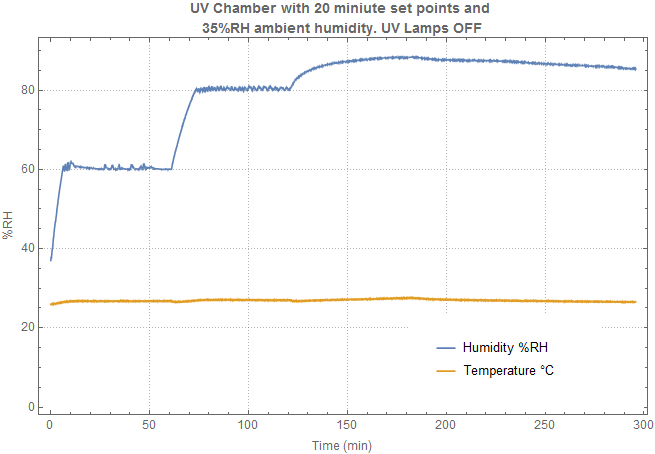
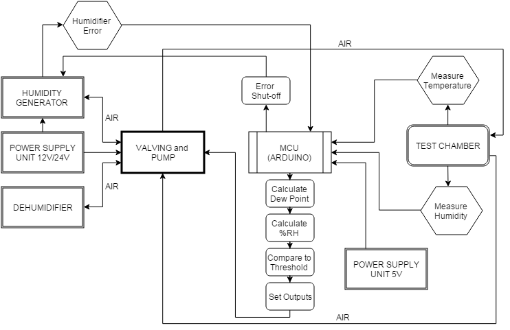
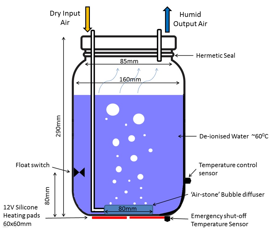
Humidity control is required for both chambers. For the UV chamber preliminary testing shows that the humidification system can raise the humidity level in the chamber to 80% in under 5 minutes from an ambient of ~35%RH.
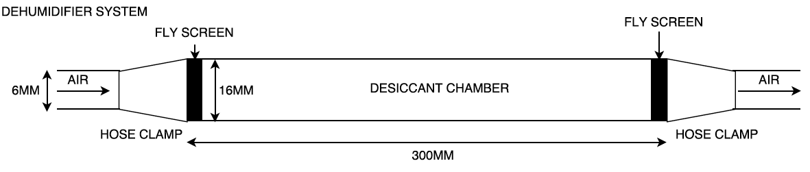
With the testing parameters used the Humidity system struggled to achieve 90%RH in the given time. The dehumidifier is effective, but slow. It is effective at maintaining a low ambient humidity, but not rapidly lowering the humidity level.


Humidity test for UV chamber. 20 minute set points at 60%RH, 80%RH, 90%RH and 70%RH Blue - Relative Humidity Orange - Temperature
Humidity test for UV chamber. 20 minute set points at 60%RH, 80%RH, 90%RH and 70%RH
Blue – Relative Humidity
Orange – Temperature

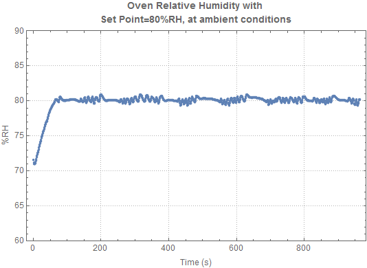
We can see that control is excellent. Achieving tolerances below +-1%RH. Additionally, we can see that the humidifier has minimal impact on the temperature of the system.


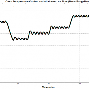
For the oven we can see that control is also excellent. Multiple temperatures are yet to be tested.

80%RH Set Point. Shows the high precision of control within +-1% RH


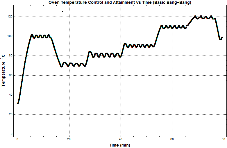
Temperature Control Tests: 

Temperature is being controlled by a simple Bang-Bang control algorithm. A PID algorithm has also been implemented and tested, but results are still poor due to additional parameter tuning required.

The graph below illustrates temperature control within the oven with 15 minute set point intervals and no insulation. Insulation has been added since this preliminary test. We can see we easily achieve the required temperature of 120C, and can control temperature within +-2C.  With insulation and a tuned PID it is expected that these results will improve. However, this test confirms the core functionality of the temperature system.

This graph illustrates the temperature within the chamber with Bang-Bang control.

Ultraviolet (UV) System: 

The UV system is designed to output in the UV-B spectrum, to maximise degradation. Initial tests have shown that UV-B levels within the chamber are approximately equal to that of Peak Sunshine on a Hot Summers day in Perth. This corresponds to an output of 3mW/cm^2.

Output is fully controllable between this maximum value and 20% of this maximum.
We had hoped for an output of approximately 5 times this.

Master Wiring Diagram

ALT Wiring Diagram

Above is the Master Wiring Diagram. This schematic details all the electrical connections required for the ALT project. Additionally, it labels all the micro-controller pins required. The Arduino Mega is used to process all I/O functions, while the Arduino Yun manages data-logging functionality.

Sub-systems have been kept together and connections spaced out to aid debugging. Certain time critical functions are attached to interrupt pins, such as the Door switches and safety resets.
Finally, as a fail-safe, certain sensors report to both the Arduino Yun and Mega. This allows either micro-controller to reset the other in case of an error or lock up. Each processor also has control of safety critical functions and can cut power if required, minimizing risk.

-Rohan

Progress Update: Humidification System Design

The Requirements Analysis and Design Document has been completed! From this the final designs and schematics of the various subsystems have been completed. In this post we look at some of the details of the Humidification System.

Humidification System: 

The following block diagram gives an overview of the system and it’s various components.

Block Diagram Summary of Humidification System

In reality, however, there will be two test chambers connected to other system elements, all controlled through the MCU and the valving.

Humidity Generator: 

Several different humidity generation schemes were considered, but the final design was chosen based on Reliability, Cost, Portability and Safety considerations.

The final design is an active bubble humidifier, which humidifies air by bubbling it through a warm water bath. This design is highly reliable and safe. It can be operated completely on DC voltages and components are easily sourced and cheaply available.

The final design for the Humidity Generator. Air is bubbled through warm/hot water and is pumped into the test chambers. The entire air path is closed, allowing humidity to build upon itself (increasing efficiency), retain test chamber heat, and reduce potential for harmful fumes escaping the test chamber.

Dehumidification: 

In order to conduct tests below ambient humidity a dehumidification system is required. After considering multiple dehumidification options a replaceable and recyclable chemical desiccant was chosen.

A chemical desiccant 'snake' is used for dehumidification.
A chemical desiccant ‘snake’ is used for dehumidification.

A silica gel desiccant was chosen due to its easy and cheap availability, excellent absorption characteristics and high temperature operation.

Humidity Valving: 

A single Humidity Generator and Dehumidifier needs to be able to service both test chambers. In order to achieve this a valving system is required to switch airflow as required. High temperature valves are required due to oven operating temperature. The system is also low pressure, requiring direct acting valves. Single way valves were chosen for cost, simplicity and sourcing reasons.

The valving and tubing for the humidification system is summarised in the above pneumatic schematic.
The valving and tubing for the humidification system is summarised in the above pneumatic schematic. “Diode Symbols” represent one-way check valves, “switch symbols” represent direct acting, one-way solenoid valves. Y-connectors are used to join 3 tubes together.

Humidification Valve Driver: 

In order to control all these valves, an amplification circuit is required to convert the MCU signal into power for the solenoids. Additionally, in order to minimise the number of MCU pins required a High Power Shift Register and Relays are used to convert a serial 5V signal from the MCU to a parrallel 12V signal to drive the solenoids. This electrical schematic is shown below.

Electrical Schematic of the circuit required to amplify and interpret the MCU signal into a power signal to drive the Solenoid Valves. The circuit also contains elements to amplify and drive the DC Air Pump as well as the Heaters for the Humidifier.

Construction: 

Most of the components for the humidification system have arrived and construction is well under way.

Until next time!
-Rohan

Michael's First Post

The Accelerated Life Test Rig project has been super-charged with the arrival of a team from Electrical Engineering to assist with the power supply and electronics. Things are now powering ahead