
System Health lab student takes Runner-Up prize for best UWA Electrical Engineering presentation 2015 for his work on LED sensors
Creating a richer university experience for digitally savvy students

System Health lab student takes Runner-Up prize for best UWA Electrical Engineering presentation 2015 for his work on LED sensors
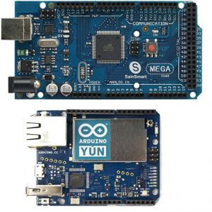
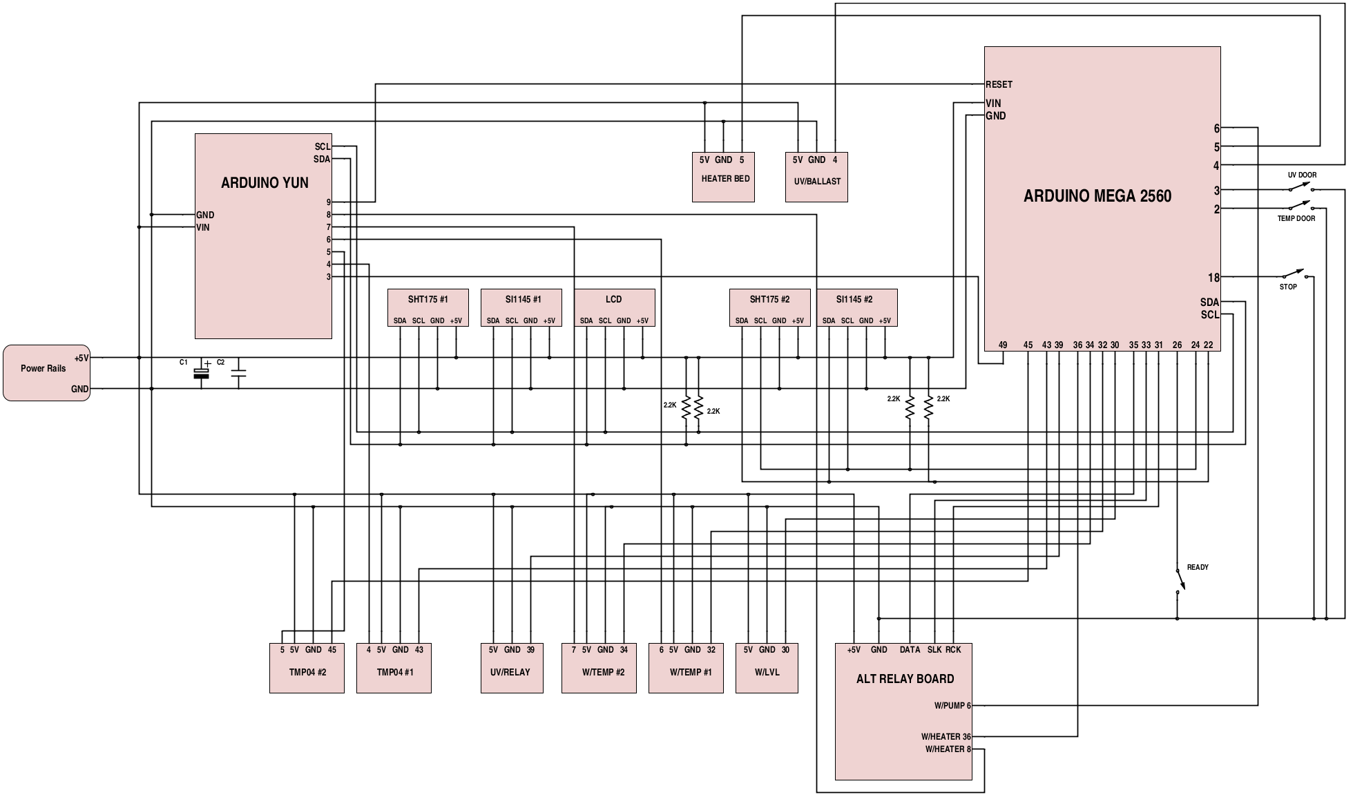
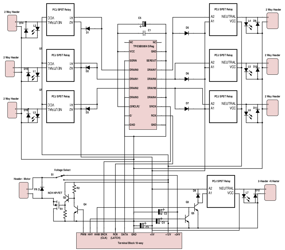
Above is the Master Wiring Diagram. This schematic details all the electrical connections required for the ALT project. Additionally, it labels all the micro-controller pins required. The Arduino Mega is used to process all I/O functions, while the Arduino Yun manages data-logging functionality.
Sub-systems have been kept together and connections spaced out to aid debugging. Certain time critical functions are attached to interrupt pins, such as the Door switches and safety resets.
Finally, as a fail-safe, certain sensors report to both the Arduino Yun and Mega. This allows either micro-controller to reset the other in case of an error or lock up. Each processor also has control of safety critical functions and can cut power if required, minimizing risk.
-Rohan
The Requirements Analysis and Design Document has been completed! From this the final designs and schematics of the various subsystems have been completed. In this post we look at some of the details of the Humidification System.
Humidification System:
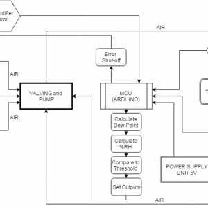
The following block diagram gives an overview of the system and it’s various components.
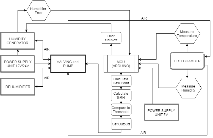
In reality, however, there will be two test chambers connected to other system elements, all controlled through the MCU and the valving.
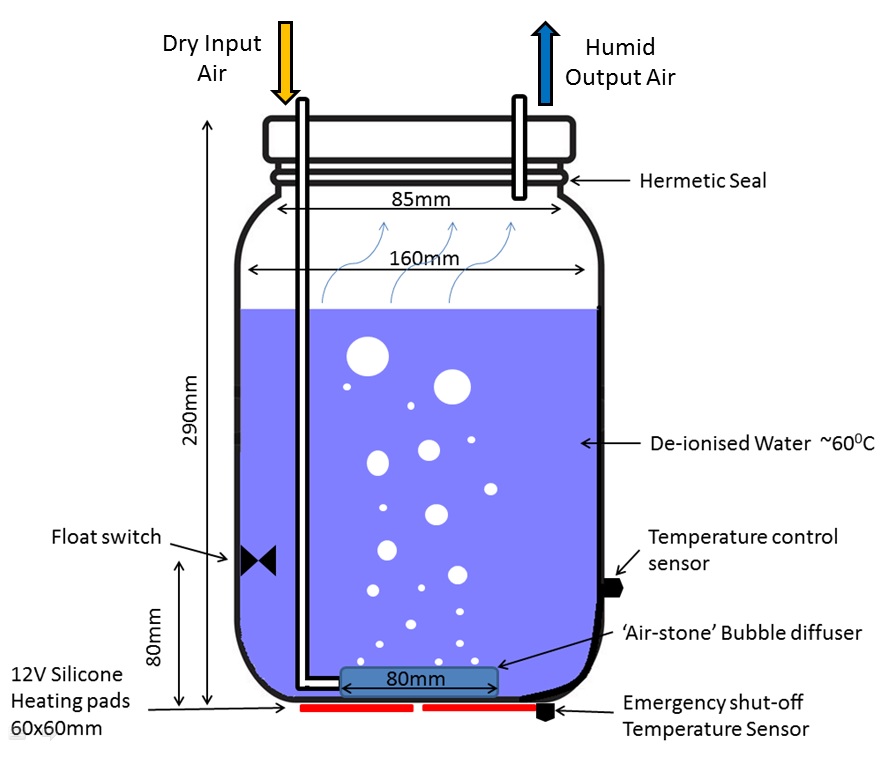
Humidity Generator:
Several different humidity generation schemes were considered, but the final design was chosen based on Reliability, Cost, Portability and Safety considerations.
The final design is an active bubble humidifier, which humidifies air by bubbling it through a warm water bath. This design is highly reliable and safe. It can be operated completely on DC voltages and components are easily sourced and cheaply available.
Dehumidification:
In order to conduct tests below ambient humidity a dehumidification system is required. After considering multiple dehumidification options a replaceable and recyclable chemical desiccant was chosen.
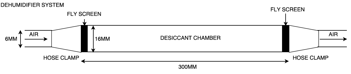
A silica gel desiccant was chosen due to its easy and cheap availability, excellent absorption characteristics and high temperature operation.
Humidity Valving:
A single Humidity Generator and Dehumidifier needs to be able to service both test chambers. In order to achieve this a valving system is required to switch airflow as required. High temperature valves are required due to oven operating temperature. The system is also low pressure, requiring direct acting valves. Single way valves were chosen for cost, simplicity and sourcing reasons.
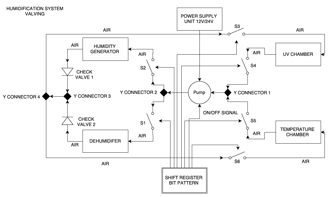
Humidification Valve Driver:
In order to control all these valves, an amplification circuit is required to convert the MCU signal into power for the solenoids. Additionally, in order to minimise the number of MCU pins required a High Power Shift Register and Relays are used to convert a serial 5V signal from the MCU to a parrallel 12V signal to drive the solenoids. This electrical schematic is shown below.
Construction:
Most of the components for the humidification system have arrived and construction is well under way.
Until next time!
-Rohan
You must be logged in to post a comment.